

Alasdair’s Engineering Pages © A. N. Beal 2025 www.anbeal.co.uk


www.anbeal.co.uk


The Structural Engineer, Vol. 84 No. 21, 7th November 2006
Columns, sway frames and BS 5950-
Alasdair N. Beal BSc, CEng, MICE, FIStructE (Thomasons LLP)
Synopsis
BS 5950-
Introduction
Until 1985, designing a steel frame was quite simple: it was analysed at working loads and there were two basic load combinations to consider: Combination 1 (dead load + live load, normal permissible stresses) and Combination 2 (dead load + live load + wind load, 25% overstress allowed). Unless there was a horizontal live load, there was no need to consider lateral loading and frame sway in Combination 1; in Combination 2 a simple first order analysis of wind moments was usually regarded as sufficient. Then (as now) beams were usually designed as simply supported for vertical loads and the frame would either be braced to resist wind loads, or else it would be designed as a sway frame, with the connections designed for the resultant wind moments. The steel design code, BS 449, had a reputation for producing economical, safe designs and was used to design many light, slender structures.
When the ‘limit state’ code BS 5950 appeared in 1985, this not only introduced factored loads but also a new loading condition: in addition to the usual Combinations 1 and 2, Cl. 2.4.2.3 required that the structure should also be checked with normal dead and live loads combined with a ‘notional horizontal load’ of either 0.5% of dead plus live load or 1% of dead load (whichever is greater). The purpose of the new loading was stated to be ensure that the structure was ‘adequately stiff against sway’ but the loads were applied as ultimate values and there was no deflexion check.
The load factors for the new loading were set as 1.4DL+1.3LL, intermediate between the 1.4DL+1.6LL of Combination 1 and the 1.2DL + 1.2LL of Combination 2. Engineers generally took the view (probably correctly) that as long as the design wind load exceeded the ‘notional horizontal load’ this new load combination could safely be ignored.
The 1990 revision of BS 5950 introduced numerous minor amendments to correct errors and anomalies in the original code. However it also included a significant change to Cl. 2.4.2.3: the load factors to be used with the ‘notional horizontal load’ were increased from 1.4DL + 1.3LL to 1.4DL + 1.6LL. The ‘notional’ horizontal forces effectively became part of Combination 1 and could no longer be ignored. In theory this amendment should have transformed the design of unbraced steel frames, making calculations more complicated and designs more conservative. However in practice nothing much changed: it seems that most engineers simply ignored the new loading requirements and carried on as before.
BS 5950-
‘Where moment resisting joints are used to provide sway stiffness, unless they provide full continuity of member stiffness, their flexibility should be taken into account in the analysis.’
Unless the connections in an unbraced frame are completely rigid (i.e. fully welded connections, or else HSFG bolts or close tolerance bolts in shear) it seems that a full second order frame analysis (with allowance for connection flexibility) is now required for basic Combination 1 design. This opens up exciting new sales opportunities for computer software companies but for practising engineers it is a major headache. Some have responded by ignoring the new requirements or else changing to BS 449. However committed BS 5950 users now face an uncomfortable choice: they must either spend a lot of money and time acquiring advanced new computer analysis programmes and learning how to use them, or else they must give up designing unbraced steel frames.
Often wind bracing in a building would obstruct a window or opening and engineers have traditionally solved the problem by designing the frame connections to carry wind moments or else by adding a wind portal. Now they must either tell their clients that they can’t do this any more, or else that it is a very complex matter which requires advanced computer analysis (and a design fee to match). Perplexed clients wonder why the steelwork designer of today finds it so difficult to do something which used to be regarded as simple. If the new requirements are correct, there must also be a worry that existing unbraced steel frames designed to previous codes may be unsafe.
Columns in BS 5950-
The 2000 edition of BS 5950 was a major revision and large parts of the code were rewritten. Unfortunately some of the new clauses were badly draughted.
(a) Cl. 4.7.1.1 defines the ‘segment length’ of a column as ‘the length between the points at which it is restrained against buckling ...’. This means that for a cantilever column the segment length is infinite, so its effective length must be infinite and its strength must be zero. This is wrong.
(b) Cl. 4.7.1.2 states that only shear diaphragms or triangulated bracing are acceptable as positional restraints to columns, implying that portal bracing is not allowed. This contradicts Cl. 2.4.2.3, which states that resistance to horizontal forces can be provided using ‘cantilever columns’ or ‘moment resisting joints’.
(c) Cl. 4.7.2 (1) says that columns in a ‘continuous structure’ may be designed using Appendix E effective length coefficients instead of the standard Table 22 coefficients. However the Appendix E coefficients are only valid for frames with perfectly rigid beam/column connections (i.e. either fully welded, or else with HSFG bolts or close tolerance bolts acting in shear). Unfortunately the code does not make this clear: Cl. E.1 only states that beam/column connections need to be ‘moment resisting’. If Appendix E coefficients are used to design columns with ordinary bolted connections, their effective lengths will be underestimated and their strengths will be overestimated. This could be dangerous.
(d) Cl. 4.7.3 Table 22 refers to a column which is held in position at both ends (i.e. in a braced frame) as ‘non-
The above points clearly require attention.
Sway frames
The main concern of the present paper is the effect BS 5950-
Traditional design of a sway frame under vertical loading relies on code effective length factors and column permissible stresses to provide frame stability. BS 5950-
Cl. 2.4.2.3 states that the purpose of these notional horizontal loads is ‘to provide a practical level of robustness against the effects of incidental loading’ but it does not explain why they need to be applied in both Combination 1 and Combination 2, or why two different values need to be considered. On the face of it, Combination 2 would be a more logical place to deal with ‘incidental loading’ than Combination 1. However the load factors which are specified in BS 5950-
Strangely, Cl. 2.4.2.4 gives a completely different explanation of the purpose of the Combination 1 notional horizontal load, stating that its function is ‘to allow for the effects of practical imperfections such as lack of verticality’.
The contradiction between these two clauses is troubling: their explanations of the purpose of the Combination 1 notional lateral load cannot both be correct. For the purposes of the present paper, it will be assumed that the correct explanation is the one given in Cl. 2.4.2.4.
Why 0.5%?
The notional horizontal load of 0.5% of total vertical load appears in two places in BS 5950-
A notional horizontal load of 0.5% of vertical load has the same effect as columns out of plumb by H/200, i.e. 15mm in a 3m storey height, or 100mm in the height of a 20m building. This is well outside the normal erection tolerances for steel columns: BS 5950-
Column analysis -
There are three basic approaches to the analysis of a pin ended column:
(a) linear analysis, which ignores second order effects and initial imperfections,
(b) Euler’s buckling analysis, which includes second order effects but ignores initial imperfections and
(c) Young’s buckling analysis, which includes second order effects,initial imperfections and eccentric loads and was the basis for the Perry-
Over the years, successive editions of BS 449 have used various versions of the Perry-
(a) the formula allows fully for second order buckling effects and
(b) factor η in the formula allows for column initial imperfections.
Table 1 shows the values of η which have been used by different editions of BS 449 and BS 5950. It also shows the corresponding initial bow (co) in the column, expressed as a proportion of the column length (L). The values are tabulated in terms of L/r, where r = radius of gyration in the plane of buckling. (In some code editions η varies with column slenderness). BS 5950 gives four different column curves but for most practical purposes only curves (b) (I section y-
Most practical structural columns in sway frames are in the range L/r = 50-
Sway frame analysis
Traditionally, buckling analysis in the UK usually considers a pin-

Fig. 1
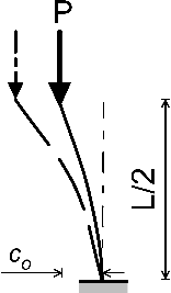
Fig. 2 Buckling of cantilever ‘model column’
Both approaches are equally valid and they give the same results: the cantilever column (effective length = 2 x column length) can be thought of as simply the top half of a pin-
(a) all second order buckling effects; and
(b) the column being out of plumb by co/(L/2) = 2(co/L).
Therefore if the column is an H section, the BS 5950 design stresses include an allowance for it being up to 2 x 0.002L = 0.004L out of plumb (0.4%); if it is an I section (or if the design is to BS 449), the design stresses allow for it being up to 2 x 0.0014L = 0.0028L out of plumb (0.28%). Therefore the standard BS 5950 or BS 449 column design stresses already include a realistic allowance for the column being out of plumb and also allow for all second order buckling effects, without any need to apply the notional horizontal force and second order analysis required by BS 5950-

Fig. 3 Fixed-
It could be argued that the above analysis only applies to a single cantilever column. However if we take two cantilever ‘model columns’, invert one and place it on top of the other, this creates a classic unbraced fixed-

Fig. 4 Sway frame
If we then consider a full frame (Fig. 4), it can be seen that the same principles and conclusions apply.
Of course it could be argued that real frames do not have perfectly rigid beams (although in a sway frame the beams will usually be stiffer than the columns). However BS 5950 gives recommendations for estimating the effective length of an unbraced column which is fixed at its base and fixed in direction at its head (1.2L), or partially restrained in direction at its head (1.5L), or unrestrained in direction at its head (2.0L). No figure is given in the code for a sway column with stiff beams at top and bottom but an effective length of 1.5L would be reasonable for this situation.
These increased values of effective length reduce the buckling strength of the column, allowing for joint rotation at the column ends, and they also give an increased allowance for the columns being out of plumb. Once more, it appears that standard design using normal column design stresses already has the relevant issues covered and there is no need to apply additional horizontal forces and second order analysis as required by BS 5950-
Conclusions
* Where a sway frame is being analysed and designed from first principles, rather than using normal column design rules, the requirements of BS 5950-
* Standard BS 5950 or BS 449 column design rules and allowable stresses already include adequate allowances for out of plumb and second order effects in a sway frame. The additional forces and second order analysis required by Cl. 2.4.2.4 and 2.4.2.7 amount to double-
* The above arguments do not apply to braced frames. In these it is important to ensure that the bracing is stiff and strong enough to resist any lateral forces generated by the structure being out of plumb. If this is dealt with in load combination 1, a lateral load of 0.15% of total vertical load would give an appropriate allowance for a normal steel frame. However this would be unnecessary if the horizontal forces required by Combination 2 are larger (see below).
* Although extra allowances for imperfections and second order effects are unnecessary for normal column design in a sway frame, a conservative approach should be taken when calculating design moments for the beam/column connections and full allowance should be made in these for moment magnification by the ‘P-
* Where the wind loading on a structure is low, in theory a design could be produced which was safe and stable under normal loadings but had limited robustness and ability to resist accidental loadings etc. It would be sensible to set a minimum value of lateral loading in load Combination 2 to cover this; a minimum horizontal force of 0.5% of total vertical load would probably be reasonable for this purpose. However if this is applied, there is no need to also apply the alternative of 1% of dead load as well.
* Many of the detailed recommendations for column design in BS5950-
Notes and References
1. Beal, A. N., ‘Who Invented Young’s Modulus?’, The Structural Engineer,78/14,18 July 2000
2. In theory it could be argued that the BS 449 allowance for imperfections is rather low for columns with L/r 50. However increasing co/L for these from 0.0004 to 0.0008 would only reduce the column capacity by about 4%. This would still leave a safety factor of 1.7 x 0.96 = 1.63, which is still adequate, so the problem is not significant.

The original copy of this paper is available from
|
|
|
|
Assumed init. |
imperfection |
co/L |
|
Code |
|
η L/r |
50 |
100 |
150 |
|
BS 449:1959 |
x- |
0.003L/r |
0.0025 |
0.0025 |
0.0025 |
|
|
y- |
|
0.0015 |
0.0015 |
0.0015 |
|
BS 449:1965 |
x- |
0.3(L/100r)² |
0.0013 |
0.0025 |
0.0038 |
|
|
y- |
|
0.0008 |
0.0015 |
0.0022 |
|
BS 5950(b) |
H x- |
0.0035(L/r - |
0.0019 |
0.0024 |
0.0026 |
|
|
I y- |
|
0.0011 |
0.0014 |
0.0016 |
|
BS 5950(c) |
H y- |
0.0055(L/r - |
0.0018 |
0.0023 |
0.0024 |
Table 1