

Alasdair’s Engineering Pages © A. N. Beal 2024 www.anbeal.co.uk


www.anbeal.co.uk


Verulam, The Structural Engineer Vol. 70, No. 12, 16 June 1992
Beam deflections made easy
Mr A. N. Beal, of Leeds, has sent us a note proposing a simple procedure for the approximate hand calculation of deflections in steel beams. While his contribution has proved too long to be included in Verulam in its entirety, a shortened version may interest many readers. Mr Beal points out that, while the calculation by hand of bending stresses in a beam is not usually difficult, the calculation of deflections may be much more laborious. Since it is not usually necessary to know deflections to any great degree of accuracy (within 10% probably being adequate), the following approach is suggested.
The case of a simply supported beam supporting a uniform load illustrates the approach.
If we take the deflection formula (Δ = 5WL³/384EI) and express it in terms of the bending moment (M = WL/8), it becomes Δ = 5ML²/48EI.
Now for a steel beam the elastic bending stress fbt = M/Z, where Z = 2I/D, giving fbt = MD/2I.
(Z is the elastic modulus, I the moment of inertia and D the section overall depth.)
Inserting this into the deflection formula gives Δ = 5 fbtL³/24ED. With an E of 210kN/mm² this becomes:
Δ (mm) = 0.992 fbtL²/D . . . (1)
Here fbt, L and D are in their usual units of N/mm², m and mm respectively.
For all practical purposes the formula
Δ = fbtL²/D . . . (2)
is convenient to use, easy to remember and exact to within 1%.
Mr Beal then goes on to consider other load distributions, similarly relating the central deflection Δ to the extreme fibre stress fbt giving results shown in the first column of results in Table 1. The second column gives values for fixed-
Finally, Mr Beal illustrates how his procedure may be used for complex loadings by deriving the deflection of a simply supported beam loaded as shown in Fig 1: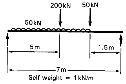
Fig. 1
Central bending moment calculated as 444.3kNm.
For the beam section, Z = 2474cm³, D = 539.5mm, giving
fbt = 179.6 N/mm².
Simple approximate deflection, using eq. (2) is
ΔAPP = 179.6 x 7²/539.5 = 16.3mm = L/429 OK.
For a more exact estimate, considering that most of the moment is generated by the central point load, we might take a coefficient nearer to the point load value of 0.8 (say, 0.85), giving
Δ = 0.85 fbt x L²/D = 13.9mm
For comparison, a precise computer analysis of the same beam gave a deflection of 13.8mm.
Therefore, for most practical purposes, we need to remember only four simple formulae for the deflections of simply supported or continuous steel beams, as shown in Table 2.
Not only do these formulae make life easy for simple uniform and point loads -
Any takers?
The original copy of this paper is available from
|
Table 2 |
Deflection |
|
|
|
Spread load |
Point load |
|
Simply- |
fbtL²/D |
0.8fbtL²/D |
|
Fixed- |
0.6fbtL²/D |
0.4fbtL²/D |
Δ = deflection (mm)
fbt = stress under maximum sagging moment (N/mm²)
L = span (m)
D = depth (mm)

|
Table 1 |
Deflection (mm) |
|
|
Loading |
Simply supported |
Fixed- |
|
|
0.99fbtL²/D |
0.60fbtL²/D |
|
|
0.95fbtL²/D |
0.56fbtL²/D |
|
|
0.89fbtL²/D |
0.51fbtL²/D |
|
|
1.01fbtL²/D |
0.66fbtL²/D |
|
|
0.94fbtL²/D |
0.53fbtL²/D |
|
|
0.79fbtL²/D |
0.40fbtL²/D |
|
|
0.74fbtL²/D |
0.38fbtL²/D |
