

Alasdair’s Engineering Pages © A. N. Beal 2024 www.anbeal.co.uk


www.anbeal.co.uk


The Structural Engineer Vol. 80 No. 9, 7th May 2002
The leaning towers of Adel: stabilising the Seven Arches Aqueduct
A. N. Beal BSc CEng MICE MIStructE, Thomason Partnership, Leeds
Synopsis
The Seven Arches Aqueduct was built in 1841-
Introduction
The Seven Arches Aqueduct is an elegant curved masonry viaduct with seven 10m span semi-
Although the Aqueduct has been disused for well over a century, it is a Grade 2 Listed Structure and a well-

Fig 1. General arrangement
History
The first waterworks for the city of Leeds was built in 1694 by Sorocold. By the early 19th century, demand for drinking water had far outstripped what this was able to supply and the citizens of Leeds relied on wells, boreholes, water carriers and the River Aire for their supplies. However by 1830 the water from the river had become unfit to drink. A submission to Parliament in 1837 referred to: ‘the water being taken from the River Aire which is greatly defiled by the refuse from the mills and dyehouses and by the common sewers and drains of the town’ [1].
In 1834 the Town Council’s Improvement Commission sought professional advice on constructing a new water supply and four civil engineers submitted proposals. The scheme of a London engineer, Henry Abraham, was selected and there were hopes that an Act of Parliament could be obtained in 1835 to enable construction to proceed. At this stage, it was generally agreed that the new supply should be owned publicly and not by a private company ‘whose sole object would be a large percentage on the capital employed’ [2].
However one of the engineers who had submitted proposals, Charles Fowler, mobilised a campaign against Abraham’s plan. The two engineers argued in the press and Fowler became involved with Tory politicians who opposed public ownership and favoured setting up a private Joint Stock Company to run the scheme. In the first municipal election in Leeds in 1835, the water supply was a major political issue: the Tories favoured Fowler’s scheme and private ownership, whilst the Liberals favoured a publicly-
Some claimed that a publicly-
On the other hand, according to the radical Leeds Times, ‘The Joint Stock Company is just a scheme for throwing the Town of Leeds bound hand and foot into the power of these men to do as to them seemeth good. The public have over them no control and their scheme is just a monopoly of one of the necessaries of life’.
Eventually the Earl of Harewood, on whose water and land all the schemes relied, brought matters to a head by refusing to co-
The new company decided to pay off both Abraham and Fowler and it appointed George Leather and Son as Engineers for the work. However, Fowler also disputed this decision and matters were not finally settled until June 1838, allowing the work to go ahead. The plans called for a new 250m gallon reservoir at Eccup, with water from there being taken through the 1.5 mile Blackmoor Tunnel (where more water was collected) to the Adel Beck. An aqueduct would carry the water across the valley and the water would then run in an open conduit to Headingley, from where it would be piped to properties in Leeds.
Curiously, the relevant Minutes of the Leeds Water Works Company (which are now held at Leeds Civic Hall) do not specifically mention the construction of the Seven Arches Aqueduct. However they do record other useful information about the progress of the whole ambitious project. In 1840 the contract for construction of the Blackmoor Tunnel was awarded to Shaw and Briggs, who were noted railway contractors. However they got into financial difficulties and were dismissed for poor performance in May 1841. Wayne and Duckett were appointed to complete this part of the work. However in his 1842 report to the Directors, Engineer George Leather did not blame all the problems on the contractors and he stated that a major cause of the slow progress was the ‘unparalleled wetness of last season’ [4].
In addition to the Blackmoor Tunnel contract, in late 1840 Shaw and Briggs were awarded the contract to construct the water conduit from Blackmoor Tunnel to Headingley. This contract must have included the Seven Arches Aqueduct and it appears that they were permitted to see it through to completion in May 1842.
When the scheme was completed, it transformed the water-
However, the increasing demand for water put pressure on the system and a drought in 1851 brought widespread complaints about shortages and poor water quality. Some politicians suggested that the problems could be solved by allowing another private water supply company to set up in competition with Leeds Water Works Company. However the arguments for public ownership finally carried the day and the waterworks were taken over by the Leeds Corporation in November 1852 for the sum of £225,730 19s. 2d [5].
Following the takeover by Leeds Corporation, a 40in (1m) diameter cast iron main was laid to replace the open conduit from Blackmoor Tunnel to Headingley. The Seven Arches Aqueduct was taken out of use in 1866, having carried water for only 24 years. In 1891, a second 42in (1.07m) cast iron water main was added, also on the east side of the Aqueduct, and in 1897 a second Blackmoor Tunnel (1.8m diameter) was constructed [6]. Construction of a third main alongside the Aqueduct was started in 1915 but halted because of World War I. It was completed in 1921 and was one of the first reinforced concrete mains in the UK. Its 42in (1.07m) diameter pipes were constructed by the Bonna process, using 0.8mm thick welded steel tubes lined with 25mm of reinforced concrete on the inside and 50mm of concrete on the outside.
In 1989 the water supply and sewage systems of England were privatised and the water supply of Leeds returned to private ownership under Yorkshire Water, after 137 years under public control. The severe drought of 1995 brought many complaints about supply problems but this time the Government resisted calls for the water supply to be returned to public ownership -

Fig 2. (bottom left) Photograph of Aqueduct in late 1890s (reproduced from postcard, courtesy of Steve Burt)
The problem
Distortion of the structure of Seven Arches Aqueduct is obvious even to the untrained eye: it is noticeably out of level and the supporting piers lean almost as dramatically as Pisa’s famous Tower. The problem appears to have been around for a long time -
In 1987, Yorkshire Water appointed Thomason Partnership to survey the structure and report on its stability and safety. We found cracking and distortion of the stonework and there was evidence of considerable foundation movement: the levels of individual piers varied by up to ±100mm and they were badly out of plumb, leaning at angles of up to 3.6°.
Analysis showed that the reason the structure is out of plumb is a problem of simple mechanics: because the viaduct is curved, the arches meet at an angle to one another on the support piers. As a result, the compressive thrust in the arches generates a lateral force at the head of each pier, increasing the bearing pressure on one side of the foundation. This pressure variation causes differential settlement of the foundation and lateral movement of the pier, which then generates more load eccentricity, more unequal bearing pressures and further movement -
Initially, no major investigations or structural work were authorised but local areas of bulging stonework were rebuilt and stonework joints were sealed to reduce water penetration. Movement in the structure was monitored from 1987 until 1993. The results of the monitoring are summarised in Table 1.
Based on the results of the 1993 survey, we concluded that piers 3, 6 and 7 were still suffering significant movement. Further measurements in 1997 confirmed significant movement at all piers, particularly 2, 3 and 6.
Investigations
Following the 1993 monitoring measurements, Yorkshire Water authorised a more detailed investigation, including trial holes to establish foundation details. Each pier foundation was found to consist of a single stone slab measuring only 2.01m x 1.78m, placed concentrically below each pier. The soil under Pier 3 was soft/very soft sandy silty stony clay.
Based on the loads and foundation sizes, it appears that the original designer probably assumed an allowable bearing pressure of 3t/ft² (322kN/m²) but failed to take into account of the lateral forces on the piers generated by the curve of the viaduct. When the structure was originally built, the theoretical bearing pressure under a typical pier would have been as shown in Fig 3a. However the lean of the structure greatly increased the bearing pressure on the outer edge of the foundation: based on the survey plumbing measurements, we estimated maximum ground bearing pressures of up to 1000kN/m² (Fig 3b). Such large load eccentricities and bearing pressures on poor soil would explain the amount of movement in the structure and clearly there were grounds for concern over its future stability.
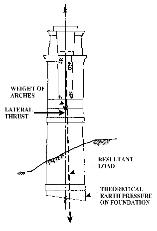
Fig 3(a) Overturning forces acting on pier -

Fig. 3(b) Pier overturning and bearing pressure (1990s)
We advised Yorkshire Water that although the current movement measured by the monitoring was not large, the structure was badly out of plumb and the theoretical soil bearing pressures below the pier foundations were far in excess of what would normally be regarded as acceptable. In these circumstances, it was likely that movement would continue and at some stage the structure would become unstable. If it collapsed, this would not only mean the loss of a historic structure -
In these circumstances, there were three possible courses of action:
* do no major work on the structure but continue monitoring, accepting that when movement became excessive, the structure would need to be shored up or else demolished;
* carry out work to stabilise the piers which showed significant movement, accepting that further work would probably be necessary in future at other piers if monitoring showed significant movement;
* carry out work designed to stabilise the whole structure.
Yorkshire Water asked Thomason Partnership to prepare a scheme to stabilise the whole structure.
First attempts at a solution
The location and nature of the structure imposed strict constraints on the schemes which could be considered:
* the Aqueduct is a Listed Structure, so the work must not affect its appearance;
* there are important water mains in the ground on both sides, and any risk of disturbance or damage to these must be kept to an absolute minimum, so no heavy machinery could be used;
* the adjacent Dales Way public footpath must be kept open throughout the work if at all possible;
* there must be no pollution of water courses or the surrounding area and damage to vegetation and wildlife must be kept to a minimum;
* the only access to the site was via a narrow track on the cast side of the valley;
* although Yorkshire Water was keen to preserve the Aqueduct if possible, it is a redundant structure, so if the cost of stabilisation was too high they might decide to demolish it instead. Because the viaducts inadequate foundations were the basic cause of the movement, underpinning was seen initially as the most promising solution, particularly as the Geological Map for the area shows rock outcropping generally. Conventional underpinning would have involved excavations below the existing highly-
Piling offered a possible alternative. The vibration from driven piles would have risked damaging the water main but perhaps it might be possible to use small diameter bored piles if they could be inserted into the space between the pier foundations and the 1921 concrete water mains. A scheme was developed using 300mm diameter bored piles with reinforced concrete brackets to connect them to the pier stonework (Fig 4). The available space for installing the piles was extremely tight: the original design drawing for the water main showed the 42in (1.07m) pipe centred 48in (1.22m) from the faces of the Aqueduct piers, leaving a theoretical gap of only 610mm and this would be further reduced at joints in the pipe. The weight of the piling rigs used also would have to be strictly limited.
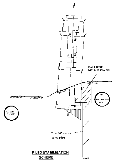
Fig 4. Piling scheme
A ground investigation with trial holes and boreholes was arranged to establish the feasibility of the scheme. According to Yorkshire Water, a repair had been carried out on the pipe near Pier 4. A trial hole confirmed that the pipe was positioned as shown on the original drawing -
Borehole casings were sunk close to each pier to reveal the depth of fill material and allow the foundation depth to be determined. The intention was then to extend these boreholes using a miniature rotary drilling rig to establish the depth to rock. The first rotary hole was drilled beside Pier 5, near to the Beck. The hole was taken down through sandy clay, gravel, siltstone fragments, sand and boulders but, by the time drilling was stopped at 16.8m, solid rock had still not been encountered.
From a practical point of view, it was clear that it would be very difficult to install piles into the restricted space available without putting at risk either the integrity of the water main or the stability of the Aqueduct. From an engineering point of view, it was clear that the ground conditions were very difficult for piling and the restrictions on vibration and equipment weight further compounded the problem. After a careful review it was concluded that a solution based on piling was no longer viable. The drilling rig was withdrawn from site, leaving the boreholes unfinished, and attention turned to alternative approaches to solving the problem.
Some of the possible alternative stabilisation schemes which were considered are outlined below:
* Flying buttresses above ground on the west side of the Aqueduct were ruled out because of their effect on its appearance. Outriggers might be placed below ground to stabilise the foundations but these had also to be ruled out because they would obstruct access to the water main for maintenance.
* Tensile wire stays could be secured on the east side of the structure to restrain it against overturning. However again the scheme was open to aesthetic objections and it would be difficult to find suitable locations for the necessary foundations for the tensile stays without disturbing the two buried water mains on this side of the structure.
* Counterweights or ground anchors could be attached to the piers by buried cantilever beams installed on the east side of the structure. Once more there were practical problems. In a scheme of this type, the lever arm needs to be as long as possible, in order to minimise the additional load imposed on the existing foundations. The slope of the ground in this case made it difficult to conceal the cantilever beams below ground and the presence of the two buried cast iron water mains limited the available lever arm (Fig 5).
* The possibility of using prestressed ground anchors to tie down the ends of the cantilever beams was considered but ruled out because of the difficult ground conditions and the risks of drilling close to major water mains. The idea of buried counterweights was investigated in more detail, but because of the lever arm limitations very large concrete blocks would be required, and somehow these and the cantilever beams would have to be excavated and concreted without causing any disturbance to the adjacent water mains -
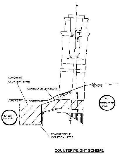
Fig 5. Counterweight scheme
‘Hoops around a barrel’
‘...when you have eliminated the impossible, whatever remains, however improbable, must be the truth’ (Sherlock Holmes in The Sign of Four by Sir Arthur Conan Doyle).
If there was no practicable way to stabilise the Aqueduct by work carried out below the ground, might it be possible to solve the problem ‘up in the air’?
As noted earlier, the curve of the structure was combining with the arch compressive thrust to generate outward lateral forces on the piers and these were pushing the Aqueduct over If a tensile force could be introduced around the same curve, it would apply inward forces to the structure, in the same way that hoops do to a barrel (Fig 6). Might a solution be possible based on this idea?
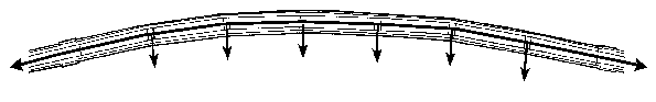
Fig 6. Schematic plan of prestressing scheme
The obvious way to apply the tensile force would be to use steel prestressing cables. If these could be placed inside the disused water conduit, with their ends anchored inside the existing abutments, they would be concealed from view and protected from both vandalism and the weather. If this scheme could be made to work, it offered the possibility of a solution which would not involve any below-

Fig. 7 Pier forces with prestressing
Analysis
The principle of the stabilisation scheme was simple: lateral forces from the curving tensioned cables generate inward lateral forces and these would balance the outwards forces generated by the existing arch compression (Fig 7). If the structure had remained plumb and undistorted, it should be possible to balance the lateral forces precisely, making the loading on the foundations perfectly concentric. However the piers had all settled and tilted, considerably increasing the eccentricity of loading on the foundations, and the movement was far from uniform: the piers all leaned at different angles and the line of the viaduct deviated significantly from a uniform curve.
In principle, the cable tension could be increased, so that it also provided compensation for the lean of the piers. However there were practical limits to the force which could be applied. At saddle positions the allowable lateral force was limited by the capacity of practical fixings into the viaduct stonework. Furthermore, if the cable tension exceeded the compression in the viaduct arches, it might trigger a sliding failure of the abutments; this problem could be overcome by installing anchor piles or ground anchors but these would increase the cost of the scheme and reintroduce the risks and problems associated with drilling in the ground near to the water mains.
Taking these factors into account, it was decided to design the scheme as ‘self-
In a masonry arch structure, the calculations for the position of the thrust line required to achieve equilibrium with the applied loads are actually quite simple, requiring only the application of the basic principles of statics. In this case, the need to consider the forces in three dimensions did complicate matters but it proved possible to break down the analysis into a series of simple components suitable for hand calculation. This process assisted understanding of the behaviour of the structure and it allowed the effects of the stressing forces and cable alignment to be clearly understood and quantified.
The alignment of the cables was adjusted laterally relative to the centre line of the viaduct in order vary the force applied at each pier, to compensate for variations in tilt and the deviations in viaduct alignment from a perfect circular curve. Various possible cable alignments were analysed and an optimised alignment was selected which reduced the maximum load eccentricity on all of the pier foundations from over 600mm to about 300mm or less. The possible recovery of the structure in response to the stressing process is not something which could be predicted accurately but calculations showed that recovery within the range that might be reasonably expected would bring further useful reductions in load eccentricity but should not change the geometry so much that new problems were created.
The final design calculations were carried out after the work had started on site and were based on a fresh plumbing survey and an accurate survey of the alignment of the duct stonework. Based on these calculations, the optimum cable alignment was determined and the specified lateral offset of the cables at each saddle was adjusted accordingly. The resulting forces and load eccentricities are shown in Table 2. (These have been calculated ignoring the beneficial effects of possible recovery of the structure following stressing.)
Design features
Ancon-
Over each viaduct pier, the space between the spandrel walls is rubble filled down to pier capstone level, so it was not possible to connect the lateral forces from the cables directly into the structure at this position. The cable saddles were therefore located at the quarter points of the span, where they could be anchored directly into the arch ring stonework. At each saddle position, an in situ concrete anchor block was formed, secured into the arch stonework by stainless steel Exchem Selfix High Load Anchors.
The manufacturers of the resin anchors, Exchem Resifix, gave very helpful advice about the likely safe working loads for anchors set into the arch stonework, allowing for edge distances and the estimated strength of the sandstone. However there was very limited relevant test data available, so when work started on site, sample anchors were set into pieces of sandstone taken from the structure and tested to failure. These confirmed that the anchors should be able to carry safely the required tensile load of 22kN. The normal installation process for Resifix High Load anchors requires the anchors to be preloaded to ‘set’ them into the resin, so every anchor was loaded to 25% over the design working load before casting the concrete anchor blocks, which gave further reassurance.
Fabricated stainless steel saddle plates were provided to locate the cables and transfer the lateral force from them into the anchor blocks; each saddle was positioned in the precise position required and bolted in place with stainless steel expanding throughbolts (Fig 8). The cables were bent around stainless steel plates in the saddles, which were gently curved to ensure low contact pressure on the cables’ protective plastic sleeves. All contact surfaces were then padded with 5mm neoprene to reduce further local pressure on the sleeves and to eliminate any risk of direct contact between the steel tendons and the stainless steel plates, which could lead to bimetallic corrosion.
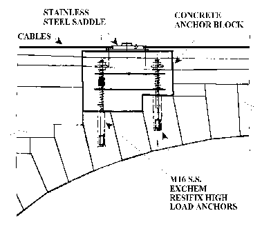
Fig. 8
At the ends of the viaduct, each abutment comprised a solid stone pier and two masonry walls behind, with a rubble core between them. To act as cable anchorages, the rubble core was replaced with a reinforced concrete core and a reinforced concrete base extending under both walls. The cable ends were cast into the reinforced concrete core formed between the two walls. The cables were arranged so that two ran straight through to live anchorages and two turned down to dead end anchorages buried deep inside the concrete core. This arrangement minimised congestion in the stressing zones and it also meant that the cable stressing losses from the two ends were balanced
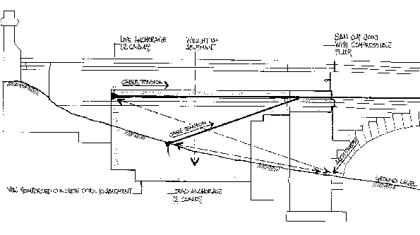
Fig. 9 Abutment
The design of the scheme was based on the assumption that the pull of the stressing cables would be balanced at the end abutments by the existing thrust from the viaduct arches (Fig. 9). However this assumption could be upset if compression was allowed to develop in the upper parts of the viaduct walls after the stressing operation. If this happened, it could offset the tension applied around the structure by the cables and negate its intended stabilising effect. To prevent this happening, movement joints were formed through the spandrel walls on the arches adjacent to the end piers by cutting through the stonework down to almost arch level and removing the rubble filling over the arch.
The design also included features to improve vandal-
Construction
Tenders for the work were invited from three Yorkshire Water ‘panel’ contractors. Morrison Construction was appointed, with a contract based on the New Engineering Contract. Before work could begin on site, agreement had to be reached with the relevant authorities for:
* a temporary diversion of the Dales Way footpath through to the south side of the viaduct during the work, so that scaffolding could be erected on the north side;
* removal of trees overhanging the structure,
* measures to protect plants and wildlife in the vicinity, including assurances that no pollution would affect freshwater crayfish in the Beck and that bat holes would be provided in the finished structure.
The contractors also had to comply with strict requirements on working areas and access:
* the only site access was via the narrow track from the east side of the valley,
* to minimise the risk of damage to the water mains, protection was required over the main on the north side, and in the vicinity of the aqueduct, plant was limited to a maximum weight of 1.5t.
The contract sum (including contingency allowance) was £118,417+VAT, with a contract period of 12 weeks. Work started in August 1998 (coincidentally about the same time as the contract to stabilise Pisa’s rather more famous Leaning Tower!).
At each abutment the east wall was taken down to allow removal of the rubble fill and construction of the slab base and concrete core; their west walls were left in place to minimise the risk of movement during the work. The west walls were underpinned, the new bases constructed and the walls reconstructed. While this was in progress, the capping slabs were lifted from the aqueduct to allow access and the rubble filling was cleared out to allow construction of the saddle anchor blocks. This was difficult work, with a very confined working space and waste having to be removed manually in buckets and barrows.
Once the resin anchor bolts had been installed into the arch stonework and preloaded, preparations were made for concreting the anchor blocks. Although the volume of concrete required was modest by normal standards, it all had to be brought to the Aqueduct in a tiny 1.5t dumper down a steep, rough track and then hoisted in buckets on to the scaffolding by rope and pulley and placed by hand.
With the anchor blocks in place, the line of the structure was carefully surveyed, final design calculations for the cable alignment were carried out and the saddle assemblies were positioned and bolted into place. The cables were then placed in position within the duct (Fig 10). The ends of the cables were threaded into position amidst the abutment core reinforcement and then the cores were concreted (Fig 11). Although the access for concreting the abutments was rather easier than at the anchor blocks high on the viaduct, the volume of concrete was larger and again it was a difficult and laborious exercise.
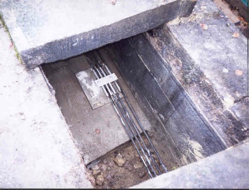
Fig. 10 Close up of saddle and anchor block with cables in duct.
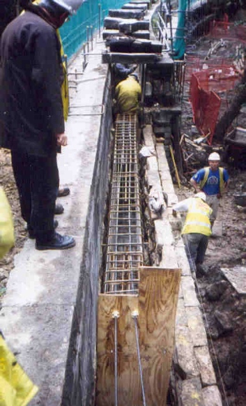
Fig. 11 Abutment construction showing cable installation along the length of the structure, making the total stressing force virtually constant. Four cables were installed, each stressed to a tension of 140kN.
The stressing of the cables was carried out on 26 October 1998. In some senses this was the most critical part of the project: although by then all the significant structural work had been completed, until the cables were tensioned, nothing that had been done would have any significant effect on the structure. The actual stressing operation was simple and proceeded uneventfully.
At an early stage in the work, it became clear that the New Engineering Contract is not ideal for this type of project. After discussion it was informally agreed that for practical purposes it would be better if Thomason Partnership acted in the role of ‘The Engineer’ as defined in traditional forms of civil engineering contract. This simplified decision-
Monitoring
Plumbing measurements were taken on the Aqueduct before the cables were stressed on 26 October 1998, and again immediately after stressing. Further measurements were taken 1 week later and then 12 months later, in November 1999. The results of these surveys are summarised in Table 4, calculated as total out of plumb from top of stonework to bottom of foundations. As can be seen, all of the piers have showed significant recovery particularly Pier 5, which was initially the farthest out of plumb.
Measurements of the end spans were taken (to check for sliding movement of the abutments). The span between piers 7 and 8 reduced by 10mm between October 1998 and November 1999, but there was no further significant movement between then and November 2000.
Conclusions
Although the principles of prestressing are well known, it is unusual to apply it to a complete existing masonry viaduct, especially when it is a Listed Structure. As explained in the paper, the reason for adopting such a radical approach was simple: all of the available alternative schemes had had to be ruled out for various reasons, leaving it as the only realistic option [7].
In the end it proved possible to conceal all the elements of the scheme inside the structure, so although fundamental alterations were made to the structure, its appearance was completely unchanged (Fig. 12). The use of standard components and minimising work below ground helped to keep the cost down.
Because of the condition of the existing structure and the precise nature of the adjustments which had to be made to the forces acting on it, almost every element of the site work was technically critical on site and required great care. In the early stages, the workmen found the project very difficult to come to terms with -
The plumbing measurements before and after stressing show that significant recovery has occurred at the worst piers, demonstrating that the scheme is working as intended. There may well be some further recovery over time. The longitudinal movement recorded in the abutments caused some concern initially but appears to have stabilised after the first year.
Because of the high ground bearing pressures under the pier foundations, the possibility of the structure suffering further movement in future cannot be ruled out. However its lateral stability should be much better now than it has been for over a century and the materials and details used in the stabilisation scheme are durable and should require very little maintenance. The project received a Historic Bridge Award from the ICE Historic Structures Panel in 2000.
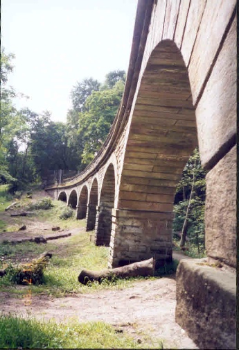
Fig. 12 The Aqueduct after completion
Acknowledgements
Thanks are due to: Graham Bowring, Steven Burt, Mike Chrimes, Stephen Garrity, David Leather and Alf Schofield; to staff at Leeds Civic Hall, Yorkshire Water, the Thoresby Society, West Yorkshire Archive Service (in Wakefield and Leeds), Leeds City Library and the House of Lords Records Office for their assistance, and to Yorkshire Water for backing the project and for giving permission to publish this paper.
REFERENCES
1. Statement of the Case in Support of the Bill, handbill 1837, Lane Fox MSS. 101.4 (Leeds City Archives), quoted in ‘The Politics of Leeds Water’ by D. Fraser in Publications of the Thoresby Society LIII, Part 1 Misc. 15, Leeds, 1971.
2. Leeds Intelligencer, 15 November 1834, quoted in Fraser op. cit., p. 52.
3. Atkinson Dibb and Bolland and John Blackburn to William Hargreaves (Hargrave), 17, 19 November 1836; Leeds Water Works, November 1836 (Thoresby Society Library, 22B 10).
4. A note in a collection of Briggs and Shaw family papers held at the West Yorkshire Archive Service in Wakefield refers to ‘Isaac Briggs (Snr) and William Shaw, who later became one of the most eminent railway contractors of the age and a friend of Stephenson and Locke, (sic) worked together on numerous occasions, pioneering railways in the early 19th century’. A note by Briggs’s granddaughter about her uncle Joseph Shaw describes him as ‘Mother’s favourite brother and Father’s greatest friend. He also was a builder & contractor and was under uncle William Shaw when building Chevet Tunnel and forward to Darfield. He was a partner with father in their first contract, which was not a fortunate venture -
5. Leeds Corporation Waterworks Undertaking Centenary 1852 -
6. Ibid, p. 30.
7. A. Schofield has recently brought to my attention details of another curved aqueduct which suffered similar problems. This was discussed in a lecture in 1954 by Mr A. L. Little of Binnie, Deacon and Gourlay at the College of Technology, Manchester. The aqueduct in question was constructed in 1885 to support an egg-

The original copy of this paper is available from
|
Pier |
Height of |
Farch comp |
earch comp |
eo/p |
etotal |
Fps |
eps |
enet |
|
1 |
3.95 |
12.2 |
20 |
154 |
174 |
10.9 |
- |
129 |
|
2 |
3.95 |
37.7 |
62 |
212 |
274 |
21.9 |
- |
183 |
|
3 |
6.15 |
36.5 |
132 |
415 |
547 |
43.8 |
264 |
283 |
|
4 |
7.65 |
31 |
150 |
319 |
469 |
25.6 |
- |
288 |
|
5 |
8.95 |
27.3 |
165 |
486 |
651 |
41.7 |
- |
303 |
|
6 |
6.05 |
36.1 |
125 |
343 |
468 |
32.8 |
- |
280 |
|
7 |
5.95 |
18 |
62 |
367 |
429 |
24.8 |
- |
283 |
|
8 |
3.95 |
18.9 |
31 |
45 |
76 |
2.7 |
- |
65 |
Table 2 Lateral forces on structure at level of centre of gravity of arches and resulting load eccentricities at underside of pier foundations
Farch comp = lateral force on pier generated by arch compression, earch comp = load eccentricity on foundation generated by Farch comp, eo/p = load eccentricity on foundation generated by out of plumb of viaduct, Fps = lateral force on pier generated by prestressing force, eps = load eccentricity on foundation generated by Fps, enet= net total load eccentricity on foundation after completion of work
Table 4: Plumbing measurements after stressing
|
Date Pier |
2 |
3 |
4 |
5 |
6 |
7 |
|
14/10/98 (before) |
275 |
513 |
402 |
553 |
446 |
432 |
|
26/10/98 (after) |
268 |
505 |
402 |
539 |
446 |
429 |
|
17/11/99 (12 months after) |
266 |
497 |
386 |
527 |
437 |
425 |
|
Total change (mm) |
- |
- |
- |
- |
- |
- |
|
Date |
Pier 2 |
Pier 3 |
Pier 4 |
Pier 5 |
Pier 6 |
Pier 7 |
|
1987 |
200 |
266 |
186 |
216 |
238 |
235 |
|
1992 |
202 |
271 |
183 |
215 |
250 |
242 |
|
1993 |
202 |
271 |
178* |
211 |
240* |
229* |
|
1997 |
208 |
274 |
182* |
218 |
244* |
228* |
Table 1: Plumb measurements on Aqueduct 1987-
* some of the stonework on piers 4,6 and 7 was rebuilt between 1992 and 1993, which affects the measurements.