

Alasdair’s Engineering Pages © A. N. Beal 2025 www.anbeal.co.uk


www.anbeal.co.uk


The Structural Engineer 89 (20) 18 October 2011
A history of the safety factors
Alasdair N. Beal, BSc, CEng, MICE, FIStructE
Thomasons, Leeds
Keywords: Safety factors, History, Design, Iron, Steel, Concrete, Codes of practice, Appraising, Eurocodes
Synopsis
In the world of computer calculations, a safety factor is a strange thing: loads and stresses are calculated to 0.01% precision -
How much of this is science and how much is ‘black art’? How have the values of safety factors been decided and how have they changed over the years?
The history of how the existing safety factors have evolved is important background knowledge for those involved in developing new codes of practice. It is also important for engineers involved in appraising existing structures. There are many issues to consider in such an appraisal [1] but if a change of use is planned, the engineer needs to understand the original design at an early stage and estimate what floor loadings it was designed for. To do this, the engineer needs to know the permissible stresses and design safety factors that were in use at the time of the original design.
An assessment of all aspects of safety in structural design would be long and complex. For simplicity, this paper focuses on the safety factors for bending, tension and compression in steel and concrete, as these usually govern the sizes of members in design and quantifying bending, tension or compression resistance of structural elements is usually the simplest way to establish what loads it was originally designed for. This paper considers how UK building code safety factors have changed from the late 19th century through to the 21st century.
Cast and wrought iron
In the 19th century, apart from masonry and timber, the main structural materials were cast iron and wrought iron. These were variable and vulnerable to flaws and very different materials from the consistent, ductile rolled steel that modern engineers are used to. A useful guide to the history of structural iron and steel sections and stresses is the Historical Structural Steelwork Handbook [2]. A useful general guide to historic structures is CIRIA Report 111 [3].
For cast iron beam design, a safety factor of 4 on an average ultimate tensile strength (UTS) of 93N/mm² (6t/in²) was recommended by some authors, giving a permissible bending tension stress of 23N/mm² (1.5t/in²). Others assumed an average UTS of 116N/mm² (7.5t/in²) but used a safety factor of 5, obtaining the same permissible stress [4]. These safety factors may strike a modern engineer as very conservative but it should be noted that they are based on average UTS and individual samples could have strengths as low as 65N/mm² [5]. In addition to strength variations, cast iron beams also suffered dimensional variations and casting flaws (Fig 1), which could further reduce the factor of safety – perhaps to 2 or less. Cast iron is brittle and can fail suddenly, so unless there is good evidence that the casting and iron are of superior quality, the standard permissible bending stress of 23N/mm² actually makes a lot of sense. (Higher stresses were permitted in cast iron bridges but these tended to be constructed to higher standards than buildings and they were often subjected to a proof loading test on completion.)
Wrought iron had a UTS of 280-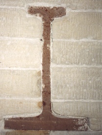 tress of 62N/mm² (4t/²) for the latter [7].
Fig. 1 End view of cast iron beam:
note bubbles in cast iron, variations in flange thickness
Pre-
In about 1883 rolled steel sections started to become available in Britain in quantity and in 1887 a catalogue was published by Dorman Long offering a full range of I-
Through most of the 20th century, steel design was based on elastic analysis and permissible stresses, although plastic design was introduced for portal frame structures in the 1960s. The minimum shape factor (ratio of plastic modulus to elastic modulus) for typical I beams is 1.11 for light sections and 1.13 for heavy sections, so a permissible elastic bending stress of Ys/1.52 is equivalent to a safety factor on plastic moment resistance of about 1.12×1.52 = 1.7.
The design of steel beams supporting floors and roofs is usually governed by bending resistance, rather than shear, and their compression flanges are usually fully restrained, so the following comparisons of beam safety factors consider restrained beams in bending.
In the early days of structural steel, permissible stresses were based on a safety factor of 4 applied to the average UTS of about 432-
In 1927, the Institution of Structural Engineers recommended a permissible stress of 124N/mm² (8t/in²) for both bending and axial compression in mild steel [10] and the same value was adopted in the first edition of BS 449 in 1932 [11]. There was no specified minimum yield stress for mild steel at the time but Mason [12] reported that, according to later research, ‘the minimum yield point for mild steel, as nearly as could be ascertained, lies between 14 and 15tons/in²’ (216-
The strength of a steel column is generally affected by its slenderness, so although a stress of 124N/mm² (8t/in²) was permitted in compression, this only applied to very short columns and in practice the permissible stress for design depended on the column stress curve adopted to allow for buckling effects. From 1909 onwards, steel columns were commonly designed using permissible stresses calculated by J. Mitchell Moncrieff. (In London the LCC regulations specified more conservative stresses [13].) These were not superseded until 1937, when BS 449 introduced new column stress curves based on Perry-

Fig. 2 BS 449 slender column permissible working stresses

Fig. 3 BS 5950 slender column equivalent permissible working stresses (Curve (c), fy = 265N/mm² and 245N/mm² with F = 1.5; fy = 221N/mm² with F = 1.7)
Pre-
Until 1959, the design of reinforced concrete was based on elastic theory, with different permissible stresses being quoted for concrete bending compression (triangular stress block) and direct compression (rectangular stress block). The subsequent change from elastic (triangular) to plastic (rectangular) stress block in bending calculations had a significant effect on compression moment resistance but made only a small difference to the lever arm of the reinforcement and the tensile moment resistance. Similarly, variations in concrete strength make a difference to the compression moment resistance of a beam and the need for compression reinforcement but their effect on tensile moment resistance is usually small.
The treatment of shear has changed considerably over the years: in earlier codes, the concrete shear strength was assumed to be constant and it was assumed that shear was either carried entirely by the concrete or entirely by the shear reinforcement. However research in the 1960s and 1970s showed that the concrete shear strength depends on the section depth and the amount of tensile reinforcement. In addition it showed that when shear reinforcement is provided the strength of this can be added to the shear strength of the concrete.
In slabs, shear is not usually critical and most beams have shear reinforcement, so the load capacity of an existing beam and slab structure is usually governed by the bending resistance based on the tensile reinforcement. Therefore the following discussion of safety factors focuses on permissible stresses in the tensile reinforcement. (Care is needed in appraisals of deep slabs and beams which have no shear reinforcement. There are also particular issues which need to be considered in flat slabs. These are discussed in more detail later.)
The load capacity of columns is governed by the compressive strength of the concrete plus any compression reinforcement provided but (unlike in steel columns) slenderness effects are usually not significant. Older codes quoted permissible stresses based on a triangular stress block for beam bending and for columns they quoted permissible stresses for direct compression. When discussing safety factors on concrete strength it is important to note that (a) because of its shape, the compressive strength of concrete in a beam or column is only about 2/3 of an equivalent test cube and (b) test cubes are usually better compacted and cured than the site concrete in columns, slabs etc., where the strength of the concrete may be around 25% weaker [14]. Based on this, the strength of concrete in a real column may only be 2/3×3/4 = 1/2 of the strength of a test cube and this needs to be taken into account when calculating safety factors.
An excellent account of the history of reinforced concrete has been produced by Sutherland, Humm, Chrimes et al [15] and in 1990 a very useful summary of the history of reinforcement properties and permissible stresses was published in Concrete [16].
Reinforced concrete was first used in UK buildings in the late 19th century and in 1897 Hennebique constructed a reinforced concrete framed building (Weaver’s Mill) in Swansea [17]. In 1911 a RIBA report [18] recommended permissible stresses for concrete of 1/3 of the cube strength (elastic bending) and 1/4 of the cube strength (axial compression); for mild steel reinforcement with a minimum yield stress of 221N/mm² (32 000psi) the permissible tension stress was 110N/mm² (16 000psi). For high tensile steel the permissible tensile stress was 0.5fy , up to a maximum of 138N/mm² (20 000psi). Thus the safety factor on reinforcement tension was 2 and if the strength of concrete in real structures (after allowing for shape effects and placing and curing) is taken as 1/2 of the test cube strength (as discussed above), then the safety factor on concrete in direct compression in columns was also about 2.
The 1934 DSIR code of practice adopted the same permissible stresses for concrete as the RIBA report for concrete but the permissible tensile stress for mild steel was increased to 124N/mm² (18 000psi) [19]. Steel quality had probably improved, so the overall safety factor was still about 2. (A British Standard specified minimum yield stress for mild steel did not appear until later.)
1939-
Thus before World War II, structural steel beams and columns and reinforced concrete beams and columns were all generally designed for a safety factor of about 2.
In November 1939, in order to economise on scarce materials in wartime, an amendment to BS 449 was published [20] ‘as an emergency measure and pending more detailed consideration of the question’. This increased the permissible bending stress by 25% to 154N/mm² (10t/in²); however the permissible stresses for axial tension and compression remained unchanged at 124N/mm² (8t/in²).
The amendment stated that ‘The permission for the increase in stress shall cease to operate as from the expiration of a period of 6 months after the end of the war, unless in the meantime the amendments have been confirmed under normal procedure as a permanent alteration to the standard’.
Based on a design yield stress of 14.3t/in², the effect of these wartime recommendations was to reduce the safety factor for beams in bending to 1.12×14.3/10 = 1.6. For members in direct tension the safety factor remained at 14.3/8 = 1.8 and the safety factor on the Perry-
No changes were made during the war to reinforced concrete permissible stresses but the Institution of Structural Engineers convened a committee chaired by Oscar Faber to review standards for the postwar period.
Post-
In 1946 Mason presented an account of the development of the draft revised BS 449. This proposed a basic permissible bending stress of 139N/mm² (9t/in²) ‘as a compromise between the prewar stress of 8tons/in² and the war-
However in 1948 (contrary to what is stated by Bates [2]) BS 15 increased minimum yield stresses for mild steel: 235N/mm² (15.25t/in²) for lighter sections and 228N/mm² (14.75t/in²) for steel >19.1mm thick. Taking advantage of these increased yield stresses BS 449:1948 retained the ‘wartime’ permissible bending stress of 154N/mm² (10t/in²) and increased the permissible stress for direct tension to 139N/mm² (9t/in²).) The new design rules provided a safety factor of about 1.65-
In subsequent years, permissible stresses were increased each time the yield stress of mild steel was increased: in 1959 the permissible bending stress was increased to 162N/mm², then in 1969 it was increased to 165N/mm² and finally in 1989 it was increased to 180N/mm² (see Table 1). However throughout these changes a safety factor of about 1.7 was retained for beams in bending and 1.6-
For slender columns, an amendment in 1964 introduced a new permissible stress curve based on revised theory and reduced the nominal safety factor from 2 to 1.7 [22, 23]. The permissible stresses were then increased again in 1969 and 1989 to take advantage of increases in the yield stress of mild steel (Fig. 2). (The 1989 edition of BS 449 also amended the permissible stresses for thick column sections.)
Post-
In 1948 a new code appeared for reinforced concrete: CP114. This maintained the prewar permissible reinforcement stresses of 124N/mm² for mild steel and 0.5fy for high yield steel but the stress limit for the latter was raised to 186N/mm² (27 000psi)[16]. Permissible concrete stresses were still 1/3 of the cube strength (elastic bending) and 1/4 of the cube strength (axial compression).
In 1957, the limits on steel stress were increased again (see Table 2) but contrary to what is stated in the literature on p. 98 [15], the safety factor remained at 2, with a permissible stress of 0.5fy. The permissible stresses for elastic bending and direct compression in concrete were unchanged but plastic ‘load factor’ design was introduced for bending calculations, with a rectangular concrete stress block at a stress of 2/9fcu = 0.22fcu.
According to the late Prof. W. B. Cranston [24], when the committee met to discuss revisions for the 1965 edition of CP114, the concrete readymix association proposed that because of improvements in production and quality control, the permissible stresses for concrete should be generally increased by 10% -
Therefore in the 1965 edition of CP114 all permissible tensile and compression stresses were increased by 10%, giving permissible concrete compression stresses (rectangular stress block) of 0.244fcu (bending) and 0.275fcu (axial compression) and a permissible reinforcement tensile stress of 0.55fy (maximum 228/207N/mm²). This reduced the safety factor on the tensile reinforcement from 2 to 1.8 and a similar figure for concrete compression (when allowance is made for shape, placing and curing of site concrete).
In 1991 CP114 was replaced by the Institution of Structural Engineers ‘Gold Book’ [25]. This retained the safety factor of 1.8, initially with a permissible stress 250N/mm² for 460N/mm² steel and later increased in 2009 to 275N/mm² for 500N/mm² steel [26]. The permissible concrete compressive stress (bending and compression) is 0.275fcu.
Summary of pre-
Therefore until 1939 the safety factor for steel beams and slender columns was generally about 2 (1.8 for tension members and short columns). During World War II (1939-
In reinforced concrete, the overall safety factor for steel tension was 2 until 1965 when, with surprisingly little thought, it was reduced to 1.8. The effective safety factor on concrete compression (after allowing for curing and shape effects) was also about 2 until 1965 and then reduced to about 1.8.
Thus the modern general safety factor for steel design came out of wartime experience, whereas the post-
Limit State Codes (1972 onwards)
In 1972, the first UK ‘limit state’ code appeared: CP110 [27] was intended to replace CP114 and also CP115 (prestressed concrete) and CP116 (precast concrete). Instead of CP114’s permissible stresses based on a global safety factor of 1.8, CP110 introduced separate partial safety factors on loads (γf) and materials (γm). ‘Limit state design’ was not just a change in calculation format: the intention was that variations in loads, materials and member strengths would be analysed statistically and then probability theory would be used to calculate new, more rational values for design loads and partial safety factors.
It is sometimes assumed that this is how the partial factors in UK limit state codes have been determined since 1972 but the truth is rather more prosaic. According to Bill Cranston [28], the CP110 committee faced a practical problem: although they supported the new limit state theory, the data which would be required to calculate new ‘rational’ loads and safety factors were not yet available. They therefore took the old code’s safety factor of 1.8 and split it into γf and γm, dividing it up on a fairly arbitrary basis. If they had chosen γf = 1.5 and γm = 1.2, this would have produced answers which were exactly the same as CP114 -
The ‘Foreword’ to CP110 confirms this: it states that ‘...insufficient relevant statistical data are available to enable a design method in complete accord with probability theory to be developed’, so the partial factor values used were ‘based on current practice’ [29]. However it was claimed that the partial factor system had the advantage that ‘Subsequently it will simplify the incorporation of amendments to the Code as new knowledge becomes available with regard to variations in loads and strengths’.
Thus when CP110 first appeared it had partial safety factors which were based on past practice and subjective judgment, just like all previous codes. However it was assumed that this would be a temporary state of affairs and soon these initial values would be replaced by rational values calculated from probability analysis.
Over the following years a considerable amount of research was carried out with the intention of turning this dream into reality. The results were collected in CIRIA Report 63, published in 1977 [30], which captured some of the excitement of the time and discussed the issues in depth. Safety factor systems with up to 5 or 7 partial factors were discussed [31], holding out the possibility of savings ‘in excess of 10%’ of materials use in construction without loss of safety [32].
In keeping with this thinking, the limit state codes which appeared in the late 1970s adopted more complex partial factor systems than CP110: the new masonry code BS 5628 [33] introduced variable materials factors and the new bridge code, BS 5400 [34] had a 3-
By the early 1980s, the promised new, more rational loadings and partial safety factors for CP110 had still not appeared but its complexity was proving unpopular with practising engineers. Theoretical problems with partial factor systems were also becoming apparent, particularly in the treatment of dead load in continuous structures [35] and statistical definitions of material strengths [36].
A draft limit state steel code was published for comment in 1981 [37]. This followed the same principles as CP110: it had γf = 1.6 (live load), γf = 1.4 (dead load) and γm was set at 1.075 so that results would be similar to BS 449. However the draft was heavily criticised by practising engineers, who saw no point in a more complicated code that offered no economic advantage. It was clear that for the new code to have a chance of being accepted, it would have to be simplified and, if possible, changed to offer greater economy than BS 449.
A BRE calibration study [38] concluded that it would be reasonable to reduce γm from 1.075 to 1.0. However in this study the factored yield stresses for Grade 43 steel were assumed as 240N/mm² (up to 16mm thick) and 220N/mm² (over 16mm), instead of the correct values based on BS 4360 yield stresses of 255/1.075 = 237N/mm² and 245/1.075 = 228N/mm². Unrestrained beams designed to the old BS 449 rules were also included in the comparisons, even though these were known to be unsatisfactory.
The BRE report also stated incorrectly (p. 23) that ‘it is recognised that column designs to BS 449 were over conservative’. In fact, for the common situation of a universal column (UC) buckling about its y-
For UCs with flanges over 40mm thick (BS 5950 (curve (d)), the BS 449:1969 permissible stresses gave a safety factor of less than 1.5 between L/r = 35 and L/r = 150 and it dropped to 1.2 at L/r = 75. However these low apparent safety factors only occur in minor axis buckling of the very heaviest UC sections at effective lengths over 3m. Research has shown that in columns with broad flanges, residual stresses locked into the flanges after rolling can reduce minor axis buckling resistance.
If the yield stress error in the BRE study is corrected and if unrestrained beams and slender heavy UC columns are excluded from the comparison, then with γf = 1.5 and γm= 1.0 BS 5950 produces beam designs which have a lower safety factor than BS 449; the same is true for UB columns and x-
Fully restrained beams are very common, so it is reasonable to assume that the BS 449 rules for these have been thoroughly tested. However when engineers design slender columns they (rightly) tend to make conservative assumptions about effective length, so the BS 449 column recommendations are less likely to have been tested ‘to the limit’ in practice.
Depending on the view taken, we could say that experience of BS 449 designs had proved a safety factor of 1.65-
Over the following years BS 5950 became accepted in use. Amendments were made to BS 5628 to correct come of its errors and anomalies. CP110 was replaced by BS 8110, which offered some simplification and also a partial solution to the problem of factored dead loads on continuous beams. However the promised new ‘rational’ values for loads and partial safety factors never materialised.
Thus, despite all that has been written about statistics and probability theory in limit state design, after decades of development the UK limit state codes for buildings still have safety factors which are based on their permissible stress predecessors. When BSI finally withdrew BS 8110 in 2010, it still had the same partial factors that had been chosen by the CP110 committee as a temporary stopgap measure back in 1972.
Existing structures
Appraisal of an existing structure may involve many different issues [1]. The nature and extent of any investigations required will depend on the structure’s condition and also on the loads that are to be applied to it. If there is no change in loading, then assessment is likely to focus on the condition of the structure and repairs for areas which have suffered damage or deterioration.
Sometimes a more detailed assessment may be worthwhile to see whether the need for repairs can be reduced by restricting loadings. However where loadings on an existing structure are to be significantly increased, a much more detailed ‘stem to stern’ check may be needed.
When checking load capacity, a good starting point is usually to check the age of the structure, measure some key members and calculate their load capacity based on design rules from the time. The original design loadings set a ‘baseline’ for the appraisal: if loadings can be kept within these, then if the structure is in good condition, only limited calculations may be needed to justify it. However if the loads applied to the structure will be greater than the original design, more detailed investigation and calculations will be required, particularly if the increase is large.
Modern codes include the results of advances in knowledge but they are also based on modern materials and construction, so their assumptions may be completely inappropriate for a historic structure. The original design rules not only allow the original design loadings to be worked out -
Thus engineers who appraise existing structures need to know how material properties, permissible stresses and safety factors have changed over the years.
Although there have been changes in its yield stress, structural steel has been a consistent, reliable material throughout the 20th century and from experience a safety factor of 1.65-
Most prewar columns will have been designed to LCC or Moncrieff permissible stresses, so again it may be possible to justify increased loading by checking them to BS 449:1937 permissible column stresses (Fig 2). (As can be seen in Fig 3, for a yield stress of 221N/mm² and a safety factor of 1.7 BS 5950 column curve (c) gives very similar results to BS 449:1937.)
However it should be noted that although permissible stresses were increased in later editions of BS 449 from 1948 onwards, these higher stresses cannot be applied retrospectively to earlier structures, as they reflected increased yield stress: modern mild steel has a yield stress 20-
In reinforced concrete, original design loadings can usually be estimated from the amount of bending reinforcement and the appropriate permissible stress for the type and age of steel. However in some situations, or if a loading increase is being considered, the engineer needs to be aware of other issues which may affect the assessment. In a structure designed to CP114, shear may be critical if there is no shear reinforcement, particularly in deeper sections and/or if the steel percentage is low. (Research in the 1960s showed a need for more conservative rules and these were adopted by CP110 in 1972.) Flat slabs designed to CP114 also need to be assessed carefully as, in addition to the shear problem, it permitted them to be designed for a total free moment of wL²/10, instead of wL²/8. (This part of CP114 was withdrawn in 1976.)
For sections with mild steel reinforcement it is not difficult to calculate bending resistance, as its permissible stress has changed very little over the years: it was 125N/mm² until 1957, when a guaranteed yield stress was introduced and the permissible stress was increased to 140N/mm². High yield steel reinforcement is more complicated: many different types have been produced over the years, with a wide variety of yield strengths and permissible stresses (see table). The yield stress of square twisted bars has been reasonably consistent but the bar sizes can be confusing†. (‘Twin twisted’ bars had a lower yield stress.) Hot rolled deformed bars are more difficult: they were produced in both ‘medium tensile’ and ‘high tensile’ steel, with yield stresses that changed considerably over the years.
Therefore when assessing the strength of a reinforced concrete structure, in addition to measuring the bar sizes accurately the engineer also needs to know the age of the structure and to identify the type of bar used, in order to determine the appropriate permissible stress.
(† Until 1964, a ‘1in. square twisted bar’ was a 1in. square but then ‘equivalent round’ bar sizes were introduced, followed in 1969 by metric sizes, which were all ‘equivalent round’. Therefore square twisted bars from before 1964 or after 1969 are reasonably easy to identify but bars from the period between may be more difficult.)
Eurocodes
In theory, all UK design codes were withdrawn on 31 March 2010 and engineers should now be using Eurocodes. These introduce a new, different partial factor system, which has been discussed in detail elsewhere [39, 40]. In addition, Eurocode 0 Annexes B and C give guidance on design methods based on reliability analysis. However Eurocode 0 section C4 notes that ‘Full probabilistic methods (Level III) ... are seldom used in the calibration of design codes because of the frequent lack of statistical data’. It states that the general basis of partial safety factors in current Eurocodes is method (a): ‘calibration to a long experience of building tradition’ [41]. In other words, despite frequent references to probabilistic methods, current Eurocodes do not have partial safety factors derived from reliability analysis -
In Eurocode 0 in the UK the basic load factors γf are 1.35 (‘permanent actions’) and 1.5 (‘variable actions’). However in load combinations another factor ψ0 may also be applied to variable loads; this is 0.7 for most floor loads. (ψ0 = 1 for storage areas, 0 for roof imposed loads and 0.5 for wind and snow loads.) If Eq. 6.10 is used for design, the design loading is 1.35DL + 1.5LL1 + ψ0 0 1.5LL2, 3....
Alternatively, the design loading may be taken as the worse of either Eq. 6.10a (1.35DL + ψ01.5LL) or Eq. 6.10b (ξ1.35DL + 1.5LL1 + 1.5LL2, 3...), where ξ = 0.925 (UK national value). Therefore in this method, if ψ0 = 0.7 the design loading is the worse of (1.35DL+1.05LL) or (1.25DL+1.5LL1 + 1.05LL2, 3...).
Thus for members supporting a single live load, Eq. 6.10 typically results in an overall load factor of 1.4-
Where a member supports more than one ‘variable action’, the situation is more complex: the reduction factor ψ0 may be applied to some of the loads but unfortunately Eurocode does not explain which ‘variable actions’ in a load combination should be considered as parts of a single ‘variable action’ and which should be considered as separate ‘variable actions’. Therefore it is not clear which of the ‘variable actions’ should be reduced by the factor ψ0. This has been discussed in detail elsewhere [42]: if every different type of floor loading can be considered to be a separate ‘variable action’, then a beam which supports areas of floor and roof with different types of imposed load could end up being designed for an overall load factor as low as 1.22. This part of Eurocode 0 needs to be clarified.
For structural steel designed to Eurocode 3 (γM= 1.0), if all the applied loads are considered as a single ‘variable action’, the overall safety factor for bending, direct tension and compression is therefore either 1.4-
For tension moment resistance in a reinforced concrete member designed to Eurocode 2 (γM = 1.15), if applied loads are considered as a single ‘variable action’, the overall safety factor for bending tension is either 1.61-
Designs to UK permissible stress codes typically have an overall safety factor of 1.8 and designs to CP110 and BS 8110 typically have an overall safety factor of about 1.65-
Eurocodes also permit the alternative option of using probabilistic reliability theory for design. However this will only be an option for specialists designing a structure where sufficient statistical data is available for all the relevant factors. Given that the standard factors in Eurocodes have not been derived probabilistically and the limited experience we have of the performance in service of structures designed in this way, anyone considering using this approach will need to proceed with caution.
The future
Reducing safety factors in design codes is rather like tip-
We know from experience that for most structural steelwork produced in the 20th century a safety factor of 1.7 is adequate. We also know that for steelwork produced and fabricated by modern methods a safety factor of about 1.5 has now been proven in use and can be used without problems.
For reinforced concrete produced in the first half of the 20th century, we know from experience that a safety factor of 2 is sufficient; for reinforced concrete produced to modern standards a safety factor of 1.8 is well proven and this has been reduced to 1.7 without problems. These factors not only provide the basis for standard designs of standard structures -
However how much lower can safety factors go without running into trouble?
For those interested in exploring this question, one possible place to start would be Eurocodes: although their safety factors are said to be based on ‘long experience’, they appear to be 5-
Urgent clarification is also needed from the Eurocode 0 committee about how its factors should be applied for different types of imposed load when more than one is present. It is also important to know that Eurocode safety factors do not include any allowance for minor damage or deterioration of the structure.
For those who wish to go further still, Eurocodes also offer the possibility of probabilistic design methods based on reliability theory. Only specialists with access to the necessary information and a clear understanding of the theory involved (and its limitations) should consider venturing into this territory on a real project. However even in this esoteric territory, past practice and experience is still a vital guide to the engineer about what can be relied on to work ... and what may not.
References
1 Appraisal of existing structures (Third edition), Institution of Structural Engineers, London, 2010
2 Bates, W., Historical Structural Steelwork Handbook, British Constructional Steelwork Association, London, 1984
3 Report 111, Structural renovation of traditional buildings, Construction Industry Research and Information Association, London, 1994
4 Adams, H., The Practical Designing of Structural Ironwork, E. & F.N. Spon, London, 1894
5 Bussell, M., SCI Publication 138, Appraisal of Existing Iron and Steel Structures, Steel Construction Institute, Ascot, 1997, Table 5.2, p. 56
6 London Building Acts 1909, quoted in CIRIA Report 111, op. cit., [3], p. 61.
7 Adams, op. cit. [4], p 188
8 Bates, op. cit. [2], p 15
9 Ibid. p 53
10 Report on Steelwork for Buildings Part 1 Loads and Stresses, 1927, Institution of Structural Engineers, London, quoted in Bates op. cit. [2]
11 BS 449-
12 Mason, J., ‘A commentary on the Draft Code of Practice for the structural use of steel in buildings’, The Structural Engineer, May 1946, 24/5, p 248 Institution of Structural Engineers, London
13 Bates, op. cit. [2] p 58
14 Plowman, J. M . et al, ‘Cores, cubes and the specified strength of concrete’, The Structural Engineer, November 1974, 52/11, Institution of Structural Engineers, London
15 Sutherland, J., Humm, D. & Chrimes, M. (Eds.) et al., Historic Concrete: Background to Appraisal, Thomas Telford, London, 2001
16 Steel Reinforcement Commission, ‘UK Reinforcement Standards, 1938 to 1990’, Concrete, 24/3, March 1990, Concrete Society, London, p 40-
17 Sutherland et al., op. cit. [15], p 68
18 Second Report of the Joint Committee of Reinforced Concrete, Royal Institute of British Architects, London, 1911
19 Report of the Reinforced Concrete Structures Committee of the Building Research Board, HMSO, London, 1933, quoted in Sutherland et al, op. cit. [15]
20 Revision to BS 449-
21 Mason, op. cit.[12], p 256
22 Godfrey, G. B., ‘The allowable stresses in axially-
23 BS 449:1959 Amendment No. 4, BSI, London, 31 January 1964
24 Cranston, W. B., personal communication
25 Recommendations for the Permissible Stress Design of Reinforced Concrete Building Structures, Institution of Structural Engineers, London, 1991
26 Ibid. Amendment No. 2, 2009
27 CP110 Part 1:1972 The Structural Use of Concrete: Part 1 Design, Materials & Workmanship, British Standards Institution, London, 1972.
28 Cranston, W. B., personal communication
29 CP110, op. cit. [27], p. 9
30 Report 63, Rationalisation of Safety and Serviceability Factors in Structural Codes, CIRIA, London, July 1977
31 Ibid. pp. 13, 14
32 Ibid. p. 18.
33 BS 5628-
34 BS 5400-
35 Beal, A. N., ‘What’s wrong with load factor design?’, Proc. Part 1, 66, Institution of Civil Engineers, London, November 1979, pp. 595-
36 Beal, A. N., ‘Concrete cube strengths -
37 The structural use of steelwork in buildings, Part 1, Simple construction and continuous construction, Code of Practice for design, 1981, 1982, Technical Committee CSB 27, BSI, London
38 Chabowski, A. J., Judge, C. J., Currie, D. M. & Roberts, E. H.: A deterministic calibration of draft British Standard BS 5950, ‘The structural use of steelwork in buildings, Building Research Establishment, Garston, 1987, p. 3
39 Beal, A. N., ‘Factors of Ignorance?’, The Structural Engineer, 79/20, 16 October 2001, pp. 16-
40 Beal, A. N., ‘Eurocodes in the Britain: the questions that still need answering’, Proc. ICE: Civil Engineering 163, February 2010, pp. 27-
41 BS EN 1990: 2002 Eurocode -
42 Beal, op. cit. [41], p. 31
43 PD 6687:2006 Background paper to the UK National Annexes to BS EN 1992-
Acknowledgments
Thanks are due to the late Professor W. B. Cranston, to Abdul Malik at the Steel Construction Institute and to the Librarians of the Institution of Civil Engineers and Institution of Structural Engineers for their assistance.

The original copy of this paper is available from
Table 1 Structural steel: material properties and permissible stresses
|
Year |
Standard |
Yield stress N/mm² (t/in²) |
Code |
Permissible Bend. Stress N/mm² (t/in²) |
Permissible Comp. Stress N/mm² (t/in²) |
|
1909 |
|
|
London C.C. Act |
116 (7.5) |
116 (7.5) |
|
1927 |
|
(216- |
IStructE |
124 (8) |
124 (8) |
|
1932 |
|
|
BS 449 |
124 (8) |
124 (8) |
|
1939 |
|
|
BS 449 |
154 (10) |
124 (8) |
|
1948 |
BS 15 |
235 (15.25), 228 (14.75) (>19mm) |
BS 449 |
154 (10) |
139 (9), |
|
1959 |
|
|
BS 449 |
162 (10.5),154 (10) (>19mm) |
147 (9.5), 139 (9) (>19mm), FoS = 2 |
|
1961 |
BS 15 |
247 (16), 232 (15) (>19mm) |
BS 449 |
162 (10.5), 154 (10) (>38mm) |
147 (9.5), 139 (9) (>38mm), FoS 2 |
|
1964 |
|
|
BS 449 |
|
147 (9.5), 139(9) (>38mm), FoS 1.7 |
|
1969 |
BS 4360 |
255, 245 (>16mm) |
BS 449 |
165 |
155, 40 (>40mm), F of S 1.7 |
|
1986 |
BS 4360 |
275, 265 (>16mm) |
|
|
|
|
1989 |
|
|
BS 449 |
180 |
170, 153 (>40) |
Table 2
Reinforced Concrete reinforcement properties and permissible stresses
|
Year |
Document |
Yield stress N/mm² (psi) |
Code |
Permissible tension N/mm² (psi) |
|
1911 |
RIBA Report |
221 (32 000) |
RIBA Report |
110 (16 000) |
|
1934 |
|
|
DSIR Code |
124 (18 000), |
|
1938 |
BS 785 |
Mild: no fy specified Medium tens.: 301 (43 700), 286 (41 400) >1in., 270 (39,200) >1½ in. High tens.: 355 (51,500), 340 (49,300) >1in., 324 (47 000) >1½in. |
|
|
|
1943 |
BS 1144 |
Cold twisted: 483 (70,000) <3/8in., 414 (60,000) Twin twisted: 345 (50,000) |
|
|
|
1948 |
|
|
CP114 |
124 (18,000), |
|
1957 |
|
|
CP114 |
138 (20,000), 124 (18,000) >1½in., |
|
1965 |
|
|
CP114 |
138 (20 000), 124 (18 000) >1½in., |
|
1969 |
BS 4449 |
mild: 250, |
CP114 |
140, 125 >40, |
|
1978 |
BS 4449 |
high yield 460, |
|
|
|
1988 |
BS 4449 |
high yield 460, |
|
|
|
1991 |
|
|
IStructE Gold Book |
140, |
|
2005 |
BS 4449 |
High yield 500, |
|
|
|
2009 |
|
|
IStructE Gold Book |
140 |