

Alasdair’s Engineering Pages © A. N. Beal 2024 www.anbeal.co.uk


www.anbeal.co.uk


The Structural Engineer, Vol. 70, No. 23/24, 8 Dec. 1992
Simple design of multibar concrete columns
A. N. Beal BSc CEng MIStructE MICE (Thomason Partnership)
F. N. Pannell BSc MSTech PhD CEng MlStructE
Introduction
Reinforced concrete columns are now often designed by computer but design charts are still a popular alternative. Many sets of charts have been published for different Codes of Practice over the years, by various authors, but most of those for rectangular columns (e.g. BS8110:Part 3 [1]and the IStructE manual [2]) cover only columns that are reinforced with four bars placed near their corners.
While this is probably the most common bar arrangement, many columns in practice -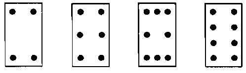
Fig. 1 Common bar arrangements in RC columns
Pannell [3] published comprehensive charts for the design of multibar columns to CPI14. These are effective but rather laborious to use; for accurate design they have been effectively superseded by the use of computer programs. However a full rigorous analysis is not always wanted and there is a need for a simple, approximate method of design.
The IStructE manual gives an approximate method for multibar columns: any bars in the side faces of the column are simply ignored and only the outer bars are considered in the analysis. Fig. 2 shows the comparison between rigorous BS 8110 analysis and this approximate method for a six-
The BS8110 handbook [4] suggests an alternative method: for calculation purposes the six, eight or more bars in the column are replaced by four bars of equivalent total area, placed at the centroid of the group of bars on each side of the neutral axis. This avoids the conservatism of the ‘green book’ method when moments are low, giving clearly better results (see Fig. 2), However, the method is still conservative and six bar columns with d of less than 0.875h (equivalent four- to below d = 0.75h.
Fig 2. ‘Green book’ and BS8110 handbook approximate analysis compared with exact analysis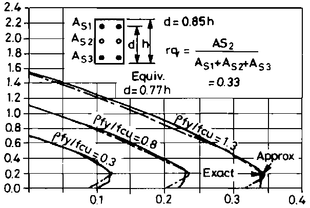
Fig 3. Proposed approximate analysis
As can be seen from Fig. 2, for a six-
During preparation of the IStructE publication Recommendations for the permissible stress design of reinforced concrete structures [5] (the ‘gold book’) the need for simple, accurate design charts capable of covering most practical situations was felt to be important. This led to the development of the method outlined here.
Proposed method
In order to refine the ‘equivalent effective depth’ method a comprehensive analysis of BS 8110 rectangular multibar columns was carried out across the whole range of reinforcement coefficients (ρfy/fcu) 0.2 to 1.4 and the range of ratios of side bars to outer bars (rq) 0.2 to 0.8. In the calculations, three layers of steel were assumed for rq = 0.0 to 0.4 and five layers of steel were assumed for rq over these values.
Fig. 3 shows the detailed comparison between exact analysis and the proposed simple method for the six-
Table 1 summarises the results of the analysis. In all, a total of 140 different arrangements and proportions of column reinforcement were analysed across the full range of axial loads and moments, and the results were compared with the equivalent four-
As can be seen, for each ratio of side bars rq the equivalent effective depth is virtually constant across the full range of reinforcement proportions and for design purposes the results can be reduced into a single table. This is given in Table 2 and Fig 4 shows the results in graphical form for convenience. This allows standard four-
When compared with the BS 8110 handbook method, the more exact figures for equivalent effective depth give an extra degree of economy but also, perhaps more importantly, they allow the standard four-
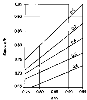
Fig 4.
BS8110: equivalent effective depths
Permissible stress design
As noted earlier, the proposed method was first developed for the IStructE publication [5]. A full analysis was again made across the whole range of reinforcement arrangements, axial forces, and moments. Again the comparison between rigorous analysis and the ‘equivalent effective depth’ four-
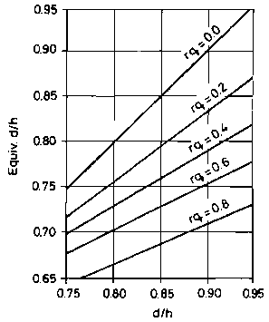
Fig 5.
Permissible stress design:
equivalent effective depths
Conclusions
Multibar rectangular concrete columns can be designed using the published curves for four-
References
1. BS 8110 Structural use of concrete: Part 3, London, British Standards Institution, 1985.
2. IStructE/ICE Manual for the design of reinforced concrete building structures, London, Institution of Structural Engineers, 1985.
3. Pannell, F. N.: Design charts for members subjected to biaxial bending and thrust, London, Concrete Publications Ltd
4. Rowe, R. E., et al: Handbook to British Standard BS8110, Palladian Pubs Ltd, London, 1987, p. 64.
5. Recommendations for the permissible stress design of reinforced concrete building structures, London, Institution of Structural Engineers, 1991.
The original copy of this paper is available from
|
ρfy/fcu= |
0.2 |
0.4 |
0.6 |
0.8 |
1 |
1.2 |
1.4 |
|
Actual d/h = 0.95 |
|
|
|
|
|
|
|
|
rq = 0.2 |
0.886 |
0.879 |
0.875 |
0.872 |
0.87 |
0.869 |
0.868 |
|
0.4 |
0.846 |
0.837 |
0.832 |
0.829 |
0.827 |
0.826 |
0.824 |
|
0.6 |
0.784 |
0.774 |
0.771 |
0.77 |
0.77 |
0.77 |
0.77 |
|
0.8 |
0.734 |
0.733 |
0.732 |
0.731 |
0.731 |
0.731 |
0.731 |
|
|
|
|
|
|
|
|
|
|
Actual d/h = 0.90 |
|
|
|
|
|
|
|
|
rq = 0.2 |
0.847 |
0.844 |
0.842 |
0.841 |
0.839 |
0.839 |
0.838 |
|
0.4 |
0.819 |
0.813 |
0.809 |
0.806 |
0.804 |
0.803 |
0.802 |
|
0.6 |
0.769 |
0.758 |
0.753 |
0.754 |
0.755 |
0.754 |
0.754 |
|
0.8 |
0.709 |
0.713 |
0.715 |
0.715 |
0.715 |
0.714 |
0.713 |
|
|
|
|
|
|
|
|
|
|
Actual d/h = 0.85 |
|
|
|
|
|
|
|
|
rq = 0.2 |
0.801 |
0.798 |
0.795 |
0.794 |
0.793 |
0.792 |
0.791 |
|
0.4 |
0.773 |
0.766 |
0.762 |
0.76 |
0.761 |
0.762 |
0.762 |
|
0.6 |
0.724 |
0.726 |
0.728 |
0.73 |
0.73 |
0.731 |
0.732 |
|
0.8 |
0.686 |
0.69 |
0.692 |
0.692 |
0.693 |
0.693 |
0.693 |
|
|
|
|
|
|
|
|
|
|
Actual d/h = 0.80 |
|
|
|
|
|
|
|
|
rq = 0.2 |
0.754 |
0.752 |
0.751 |
0.754 |
0.755 |
0.756 |
0.758 |
|
0.4 |
0.726 |
0.728 |
0.732 |
0.734 |
0.735 |
0.736 |
0.737 |
|
0.6 |
0.693 |
0.701 |
0.703 |
0.704 |
0.705 |
0.706 |
0.707 |
|
0.8 |
0.663 |
0.667 |
0.668 |
0.669 |
0.67 |
0.67 |
0.67 |
|
|
|
|
|
|
|
|
|
|
Actual d/h = 0.75 |
|
|
|
|
|
|
|
|
rq = 0.2 |
0.709 |
0.72 |
0.724 |
0.724 |
0.724 |
0.724 |
0.724 |
|
0.4 |
0.693 |
0.701 |
0.704 |
0.704 |
0.704 |
0.704 |
0.704 |
|
0.6 |
0.668 |
0.675 |
0.677 |
0.677 |
0.677 |
0.677 |
0.677 |
|
0.8 |
0.639 |
0.643 |
0.644 |
0.644 |
0.644 |
0.644 |
0.644 |
TABLE 1 -
|
Actual d/h = |
0.75 |
0.8 |
0.85 |
0.9 |
0.95 |
|
rq = 0.2 |
0.72 |
0.75 |
0.79 |
0.84 |
0.87 |
|
rq = 0.4 |
0.7 |
0.73 |
0.76 |
0.81 |
0.83 |
|
rq = 0.6 |
0.67 |
0.7 |
0.73 |
0.75 |
0.77 |
|
rq = 0.8 |
0.64 |
0.67 |
0.69 |
0.71 |
0.73 |
TABLE 2 -
(rq = side steel/total steel)
|
Actual d/h = |
0.75 |
0.8 |
0.85 |
0.9 |
0.95 |
|
rq = 0.2 |
0.72 |
0.76 |
0.79 |
0.83 |
0.87 |
|
rq = 0.4 |
0.7 |
0.74 |
0.76 |
0.79 |
0.83 |
|
rq = 0.6 |
0.68 |
0.71 |
0.73 |
0.75 |
0.78 |
|
rq = 0.8 |
0.64 |
0.67 |
0.69 |
0.71 |
0.73 |
TABLE 3 -
(rq = side steel/total steel)
