
Alasdair’s Engineering Pages © A. N. Beal 2024 www.anbeal.co.uk


www.anbeal.co.uk


Concrete February 2010
Fabric-
Alasdair N Beal, Thomasons
In 2003, the Third Edition of Concrete Society Technical Report 34 [1] was published. It brought together guidance for all types of industrial ground slab in one publication and also introduced a new design method for fabric-
For many years, the UK ‘Bible’ for designing concrete ground-
The first and second editions of Concrete Society Technical Report 34 (1988, 1994) relied on TR550 for design of fabric-
* TR550 uses elastic analysis of slab bending capacity, whereas TR34/3 uses plastic analysis.
* According to TR550, ‘a sub-
* In TR550 the safety factor on dynamic loads varies depending on number of load repetitions, to prevent fatigue failure, whereas in TR34/3 it is constant (9.6.3, p.54).
* In TR550 (p.9), assumed load transfer across a joint is 15% (single joint) or 30% (joint intersection). In TR34/3, it can be up to 50%.
Comparison
The following analysis compares TR34/3 and TR550/ ITN 11 for a slab supporting ‘Category 2’ (Medium) loading, with 3t forklifts (3.75-
ITN1 1 Tables 1-
Several points are worth noting:
* In T34/3, variations in subgrade quality do not affect load capacity.
* On a ‘poor’ subgrade, a 170mm slab would be required by TR550/ITN11 but only 129mm by TR34/3.
* In TR550/ITN11, the slab fails in bending but in TR34/3 it fails in shear (curiously, despite this, TR34/3 devotes seven pages to bending analysis and only one page to shear).
* Based on TR34/3 moment analysis, a slab on a poor subgrade would only need to be 99mm thick.
* After permitted construction tolerances (slab level ± 15mm, sub-
Analysis
When a new design method gives radically different results from past practice, it should be checked carefully. TR34/3 introduces three major changes:
* bending strength is calculated from plastic theory instead of elastic theory
* assumed load transfer at joints is increased
* slab load capacity is assumed to be the same at a joint intersection as at a single joint.
Table 2 compares allowable working loads (kN) based on bending analysis for a 150mm-
TR550 allows 15% load transfer at a single joint and 30% at a joint intersection. Two sections of TR34/3 discuss load transfer. According to 8.8.2 (p.45) friction provides 15% load transfer and steel fabric ‘typically provides 10% load transfer’. However according to 9.10, A142 mesh transfers 13.4kN/m (ultimate) over a length of 0.9 x l each side of the load (‘l’ is the radius of relative stiffness) subject to a total load transfer limit of 50% (A193 fabric transfers 18.3kN/m and A252 23.8kN/m).
Consider a 90kN forklift wheel (factored load 144kN) on a slab with ‘radius of effective stiffness’ of 700mm. According to TR34/3, load transfer at a joint would amount to 15% = 21.6kN (friction) plus 1.8 x 0.7 x 13.4kN/m = 16.9kN (fabric) = 38.5kN total (27%). However, with a 30kN forklift wheel (48kN factored), load transfer would be 7.2kN (friction) plus 16.9kN (fabric) = 24.1kN total (50%).
Thus TR34/3: a) increases load capacity in bending beside a joint; b) increases assumed load transfer at a joint; and c) says joint intersections can be ignored (8.8.2). The effect of combining these is a dramatic increase in the load that can be applied to a slab.
Analysis -
TR34/3 assumes that dowel capacity at a joint is always fully mobilised, up to the total load transfer limit of 50% (9.10.1). Is this correct?
TR34/3 Appendix E
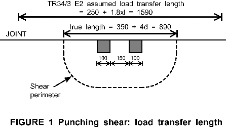
TR34/3 section 9.10 gives recommendations for load transfer at joints, based on bending analysis but it says nothing about how it should be calculated when punching shear is being considered. In the Appendix E2 worked example, the load transfer length is taken straight from 9.10, without any modification for the size of the punching shear perimeter. As a result, load transfer is overestimated and punching shear stress is underestimated.
In the example, 100mm square racking legs at 250mm c/c (combined factored load 144kN are positioned 70mm from a joint. The final slab design has d = 135, a punching shear perimeter of 1475mm and a shear capacity of 103.3kN. Load transfer is assumed across a length of 0.9 x I of joint to each side of the loads: total length 2 x 670 + 250 = 1590mm. Calculated load transfer (15% friction plus reinforcement dowel capacity) = 0.15 x 144 + 1.59 x 13.4 = 21.6 + 21.3 = 42.9kN. Thus net shear = 144 -
However, load transfer outside the shear perimeter cannot reduce shear inside the perimeter (see Figure 1). The E2 calculation should only have considered the length of joint inside the shear perimeter: 350 + 540 = 890mm. Reducing load transfer pro rata for this reduced length gives a corrected value of 890/1590 x 42.9 = 24kN and the net shear becomes 144-

Limits on load transfer -
TR34/3 9.10 assumes that (within its overall 50% limit) load transfer at a joint depends on the friction that can be developed and the dowel strength of the reinforcement. However, other potential limiting factors have not been considered.

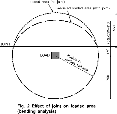
Consider a slab supporting a point load (Figure 2). If the ‘radius of relative stiffness’ defines the area supporting the load, then if l = 700mm, the area is it Π x 0.70²= 1.54m². If a joint is cut 150mm from the load, then 0.98m² of load-
Limits on load transfer -
In punching shear calculations, the load transferred across a joint cannot exceed the strength of the slab on the other side.

Figure 3 shows a slab with an effective depth of 100mm supporting a 100mm x 100mm load centred 150mm from a joint. The length of the punching shear perimeter = 400 + 1256= 1,656mm, of which 100 +418 = 518mm is on the other side of the joint. If the joint was perfectly rigid, maximum load transfer would be 31%. A real joint will have some flexibility, so it will transfer less.
Joint intersections
Many engineers will be surprised by TR34/3 8.8.1: ‘Although the theoretical load capacity at the intersection of two joints is much lower than at a single joint, experience has shown that the actual capacity appears to be as great, given the same conditions of joint opening and provision of dowels or other load-
This is simply asserted, without any supporting evidence or references. The design method in this edition of TR34 is new and produces thinner slabs than past UK practice, so how can the claim in 8.8.1 be based on ‘experience’?
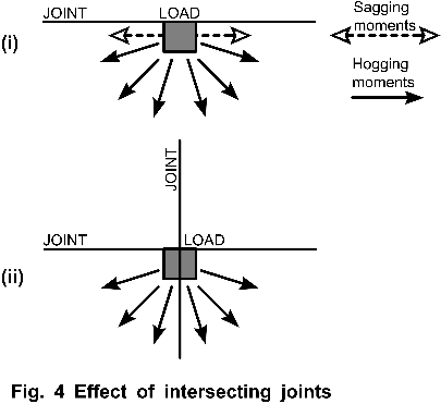
A load alongside a slab joint (Figure 4) is supported by sagging moments parallel to the slab edge and hogging moments radiating outwards from the load. What happens if another joint is cut in the slab at right angles to the first? The sagging moments and the load capacity they generate will be cut to zero, so the slab will be able to support less load. TR34/3 8.8.1 cannot be correct.

Concluding remarks
The TR34/3 recommendations for fabric-
* in a punching shear calculation, load transfer outside the shear perimeter should not be included
* consideration of loaded areas shows that maximum load transfer across a joint is about 25%, not 50%
* slab load capacity at a joint intersection is not equal to the capacity at a single joint.
In addition:
* research is needed to confirm whether fabric-
* design safety factors should be reviewed taking into account the effect of construction tolerances on thin slabs.
References:
1. CONCRETE SOCIETY. Concrete Industrial Ground Floors: A Guide to design and construction. Technical Report 34, 3rd Edition, The Concrete Society, Camberley, 2003.
2. DEACON, R.C. Concrete Ground Floors: their design, construction and finish. 3rd Edition, MPA Cement, Camberley, 1986 and 1987.
3. CHANDLER, J.W.E. Design of Floors on Ground. Technical Report 550, MPA Cement, Camberley, 1982.
4. CHANDLER, J.W.E. and NEAL, F.R. The Design of Concrete Ground-

This paper is reproduced by kind permission of
The Concrete Society
www.concrete.org.uk